-
Simerics at Turbomachinery & Pump Symposia 2021
Simerics will be participating in the 50TH TURBOMACHINERY & 37TH INTERNATIONAL PUMP USERS SYMPOSIA (TPS 2021).
TPS 2021 will be held at George R. Brown Convention Center in Houston, TX on December 14-16.Please visit us at booth # 2607 to learn about the latest developments from Simerics and to talk to our engineers.
Looking forward to seeing you at TPS2021!
-

CFD for Creo – Are you ready for Electrification?
Free Series on CFD for Engineers, Designers and Engineering Managers
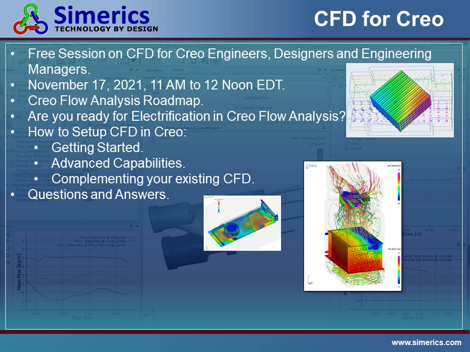
Join PTC Wednesday, November 17th at 11 am EDT for this session on CFD for Creo Engineers, Designers and Engineering Managers.
It will include:
- Creo Flow Analysis Roadmap.
- Are you ready for Electrification in Creo Flow Analysis?
- How to Setup CFD in Creo:
- Getting Started.
- Advanced Capabilities.
- Complementing your existing CFD.
- Questions and Answers
-

Simerics, Inc. and McNeel & Associates Announce Rhino Flow RT CFD Software
Rhino Flow RT enables Rhinos users to model CFD in real time
BELLEVUE, August 2, 2021 – Rhino users can now use CFD simulation software in real time as they model in Rhino by using Rhino Flow RT. McNeel and Simerics have combined the modeling strengths of Rhino with the Simerics-MP CFD strengths into one workflow and user interface in Rhino, available today. This allows Rhino users to save thousands of dollars in hardware prototypes and CFD outsourcing costs and reduces the number of design iterations and prototype cycles. Rhino Flow RT also provides the ability to view and explain to customers and colleagues how their design functions for the un-seeable physics in their models like velocity, pressure and additional natural phenomenon physics properties using Simerics-MP CFD.
By working together, Simerics, Inc. and McNeel and Associates have enabled Rhino users to use CFD without expensive CFD training so they can focus on CFD results and design solutions.
“Our development with McNeel has enabled the delivery of comprehensive and validated CFD functionality to Rhino users that wasn’t possible before,” said Rich Moore, Executive Vice President Strategy, Simerics, Inc. “With Rhino Flow RT we are bringing an entirely streamlined workflow to CFD and the Rhino design community.”
“We have added Simerics-MP software to Rhino to fulfill the Rhino community’s requests and demands to have usable CFD as a plugin option to Rhino modeling and is available through Rhino resellers. Resellers can sell CFD and provide first line support with Rhino Flow RT,” said Bob McNeel, CEO of McNeel and Associates.
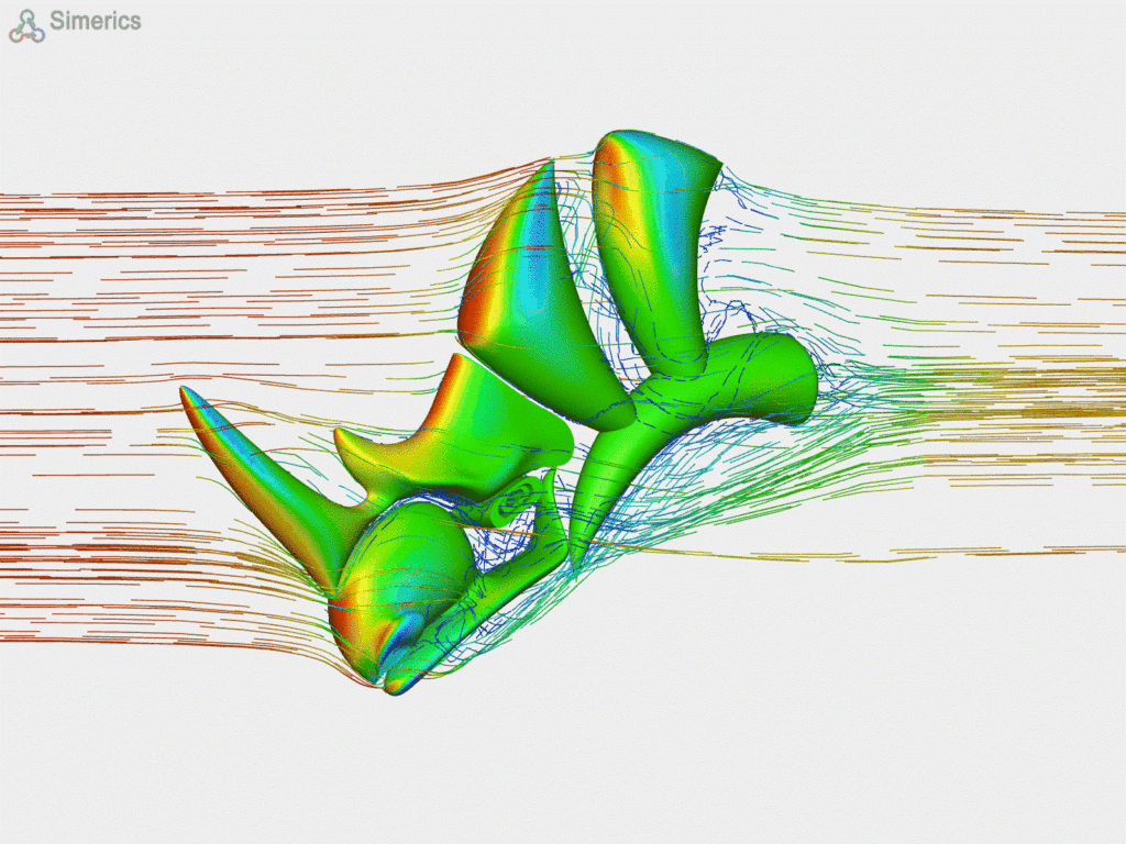
About Simerics, Inc.Simerics is headquartered in Bellevue, WA and are the developers of Simerics-MP; Simerics-MP+; Rhino Flow RT; Orca3D Marine CFD; Creo Flow Analysis; Simerics MP for Fusion; CFTurbo SMP all leading simulation products. Simerics and our partners serve several vertical industries: Auto, Aerospace, Pumps, Valves, Compressors, Marine, Heat Exchangers, Electronics and Motors, Turbine, Oil and Gas and general CFD problems. For more information please visit www.simerics.com
About McNeel and Associates
Founded in 1980, Robert McNeel & Associates is a privately-held, employee-owned corporation providing technical professionals with productive tools shaped from emerging technologies.
Contacts:
Rich Moore
978.376.1763
and
-

-

News
Page 15 / 34
